 Veteran Owned
 Veteran Owned
Measuring Thickness
When to use eddy current instruments to measure thickness
Thickness can be measured and/or monitored using a variety of methods to include surface profilometers, ellipsometers, spectroscopic reflectometers, interferometers, weight measuring, Quartz Crystal Microbalances(QCMs), and non-contact eddy current instruments. Each of these technologies has its advantages and disadvantages, eddy current technology is usually most appropriate when:
- Non-contact technology is needed
- High precision and accuracy is needed
- The material’s opaqueness/transparency make other methods of evaluation ineffective
- Volume Resistivity is known or can easy be acquired. (Note: nearly all non-contact thickness methods require reference information or special calibration)
- Inline or in-situ monitoring is needed – often times other measurement techniques cannot be used in-situ or inline
Relationship between thickness, conductance, and resistance
It is intuitive that a coating of many conductive/metallic layers will be both more conductive and thicker than a coating of one layer of conductive/metallic material. In fact, there is a near perfect correlation between thickness and sheet conductance. That is to say, if the thickness of a conductive layer is doubled, the sheet conductance nearly always doubles. When speaking in terms of sheet resistance, this is the equivalent of adding resistors in parallel.
Equation 1: Thickness adds in linearly
T1 + T 2 + T 3 = T total
Equation 2: Sheet conductance adds linearly
Cs 1 + Cs 2 + Cs 3 = Cs total .
Equation 3: Sheet resistance adds as parallel resistors
1/Rs 1 + 1/Rs 2 + 1/Rs 3 = Rs total .
Figure 1: Relationship between thickness, sheet conductance, and sheet resistance

It should be noted that eddy current instruments measure the entire “stack” of conductive layers – even if they are separated by a non-conductive layer. If the user wishes to measure only one of the layers, the user must measure as each layer is added. The sheet conductance (and therefore the sheet resistance through reciprocation) of subsequent layers can be derived by subtracting the sheet conductance of previous layers.
Sheet resistance and thickness
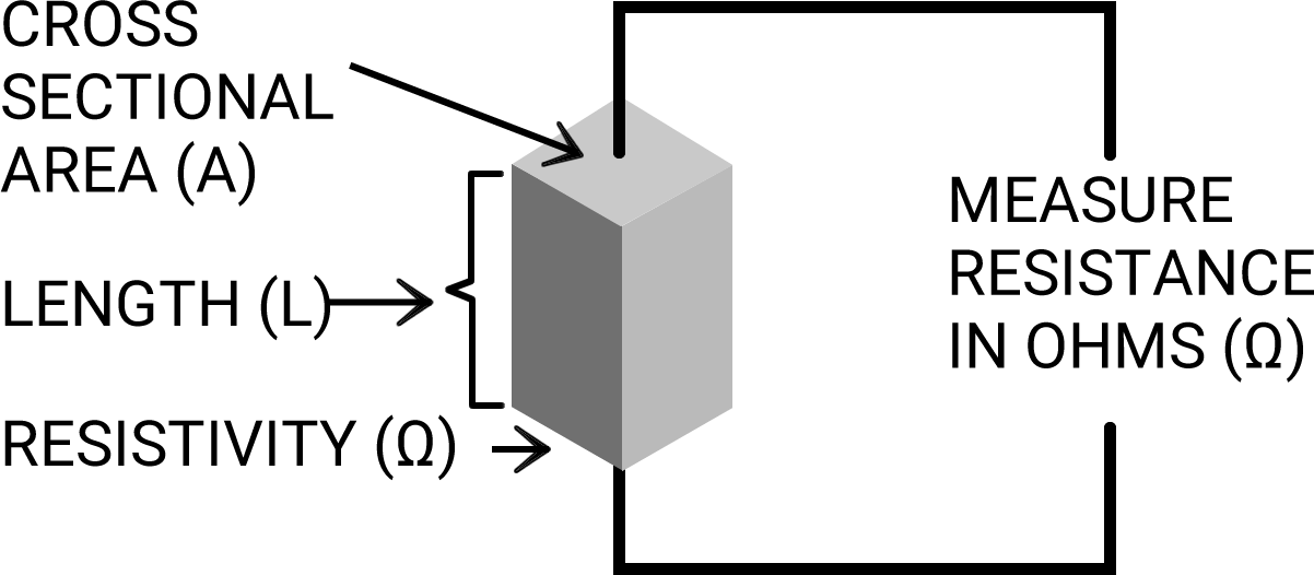
The electrical resistance (R) of an object is measured in Ohms and represented by the Greek letter Ω (omega). The resistance of a metal or a semiconductor can be measured using an ohmmeter (a common function on benchtop multimeters). The measurement of an object’s resistance can be taken with such a meter independent of the dimensions of the object or the object’s internal composition.
Figure 2: Resistance of an object
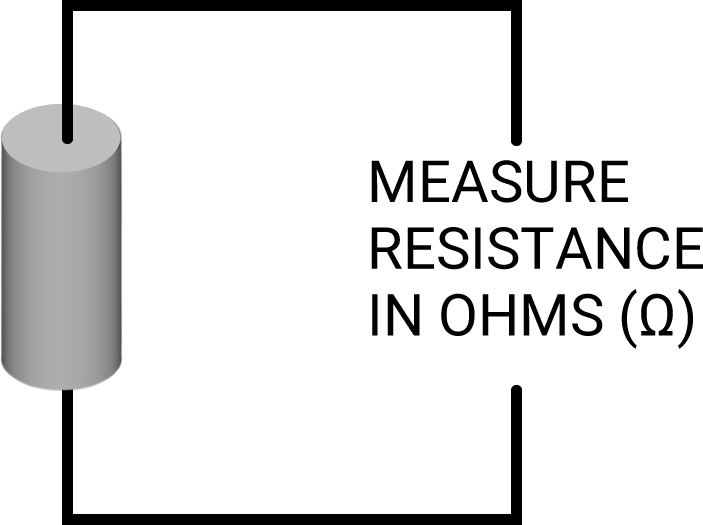
Three factors contribute to an object’s overall resistance. It is intuitive that a longer object is more resistive to electrical flow, as the electrons have farther to travel. Similarly, a narrower object is more resistive to flow, as there are fewer parallel pathways for the electrons to travel down. Finally, an object that has a material more intrinsically resistant to the flow of electrons will be more resistive. This intrinsic characteristic of a material that makes it conductive to the flow of electrons is called resistivity.
Therefore, we can say that electrical resistance (R) of an object is a result of three factors:
- Cross-sectional area of an object (A)
- Length of the object (L)
- Intrinsic properties of the material the object is composed of—resistivity (ρ)
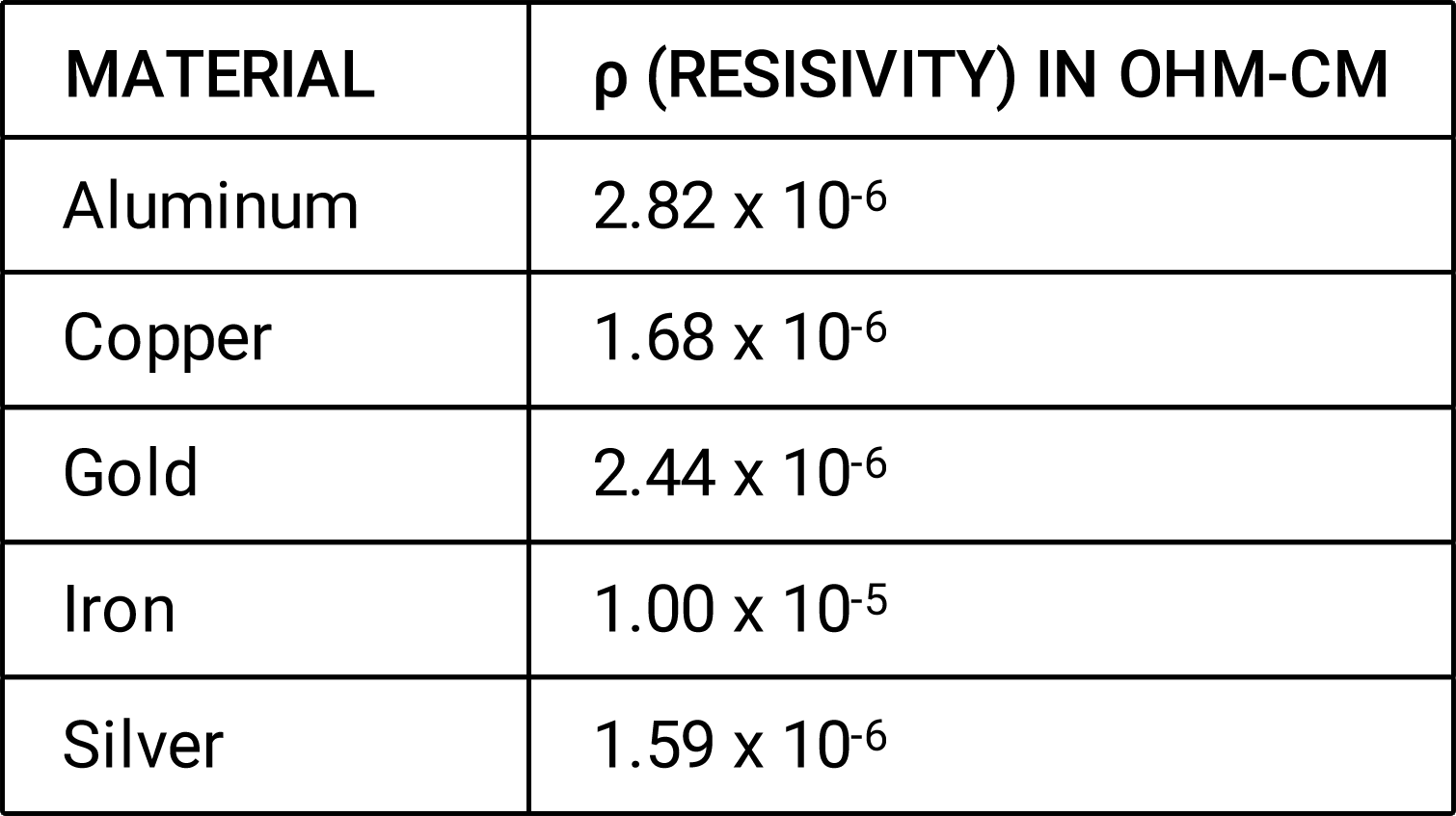
To determine the resistivity of various materials, objects composed of different materials but with the same dimensions were tested for their resistance. Table 1 shows the resistivities of some common materials.
Table 1: Resistivities of various materials
From these observations about the three factors of resistance, we conclude that resistance equals resistivity (ρ) times length (L), divided by area (A), as demonstrated by Figure 3 and Equation 4.
Figure 3: Resistance is a function of resistivity (ρ), length (L), and area (A)
Equation 4: Formula for resistance
R = ρxLA
In order to find the sheet resistance of an object, think of a square shape cut out of a doped silicon wafer, conductive film sheet, or a coated glass panel. We don’t want to have to worry about length and width along the entire plane of the material. This can be avoided by assuming a square shape. Now let’s describe the square as having a length (L), width (W), and thickness (T), as shown in Figure 4 below.
Figure 4: Sheet of resistive material
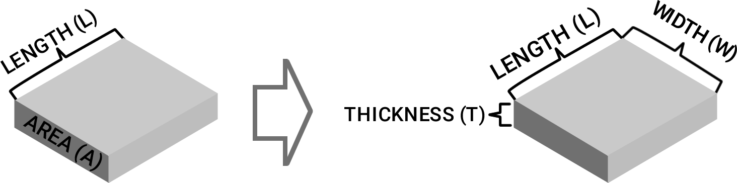
Next, let’s take our formula that relates length, area, and resistivity to resistance and transform it. This is done by substituting area (A) with width (W) times thickness (T).
Equation 5: Transforming resistance equation
R = ρxL A ⇒ R = ρxL LxW
Finally, since the material in this example is a perfect square, we can substitute length (L) for width (W). This results in the equation: Sheet resistance (Rs) equals resistivity (ρ) divided by thickness (T).
Equation 6: Formula for sheet resistance
Let L =W and consider Rs
Rs = ρxL TxL ⇒ Rs = ρ T
Knowing that sheet resistance equals resistivity divided by thickness, we can conclude that thickness equals resistivity divided by sheet resistance. Therefore, to determine thickness, the resistivity must be known and the thickness calculated by dividing resistivity by sheet resistance.
Equation 7: Formula for thickness as a function of sheet resistance
Rs = ρ T ⇒ T = ρ Rs
Example: Consider a material that has a sheet resistance of 3.00 ohms/square and a volume resistivity of .06 ohms-cm. .06 ohms-cm divided by 3.00 ohms/square equals a thickness of 0.02 cm.
Units of measurement
Delcom uses the metric unit of measurement for length or thickness called a micrometer, also called micron. Its symbol is μm or (sometimes) μ. A micron is equivalent to one one-millionth of a meter or one one-thousandths of a millimeter (1μm = 0.001 mm).
Applications that measure/monitor sheet resistance
- Transparent Conductors
- Displays
- Wires, Meshes, & Grids
- Carbon Nanotubes
- Graphene
- Thin Film Solar
- LEDs
- Low E Glass
- Smart Glass
- Thin Film Heaters
- Semiconductor Wafers
- Crystalline Solar
- Packaging
- Microwave Susceptors
- Film Capacitors
- Printed Electronics
- Batteries & Storage
- EMI & EMS
- Auto Mirrors
How eddy current instruments measure thickness
Eddy current meters work by introducing a current into the sensor’s inductor coil(s). This generates an oscillating magnetic field. When a conductive material is introduced into the magnetic field, a circular flow of electrons begins to move in the conductive layer due to magnetic induction. Eddy current technology earned its name because this flow of electrons is reminiscent of eddy current swirls in a body of water.
An eddy current instrument works by coupling the material to be tested to an amplitude stabilized oscillator. The power absorbed by the material in the oscillating magnetic field is proportional to the conductivity of the material. This power level is delivered as voltage to an analog-to-digital converter (ADC). This voltage is scaled from 0.0001 to 2.0000 voltage direct current (VDC). For a standard range meter, .0001 VDC is equal to .0001 Siemens/square.
To get to thickness, the eddy current meter digitally reciprocates sheet conductance to display the material’s sheet resistance (measured in ohms/square). At this point, the user inputted material resistivity (measured in ohms-cm) is divided by the material’s sheet resistance (measured in ohms/square). The resulting reading is a calculated value for thickness (measured in microns).
Configuring your instrument to display thickness
In order to display thickness to the user, the Delcom meter must be told what the resistivity of the material is. The meter then performs the appropriate calculations and displays the thickness of the material. This—of course—requires the user to know the resistivity of the material and input it into the meter.
There are multiple methods available to determine the resistivity of a material. These are listed here in order from most to least practical:
- Ask the supplier of your conductive material what the resistivity of the material is.
- Assume the material is a pure material or alloy and look up the resistivity value in a source such as The Handbook of Chemistry and Physics. Examples of the resistivities of some common materials are listed in table 1 above.
- Create a sample of near-perfect thickness and use an eddy current instrument to determine its resistivity. This process would require a one-time use of a precision contact thickness meter
- Use spectrometry/spectroscopy or a similar method to determine the resistivity of a material. Many testing labs can perform the task for you.
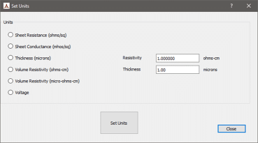
In order to measure thickness with a Delcom meter, the user must have access to Delcom software. The software might only need to be used once, but it is necessary to set the units of measurement to be displayed.
- Open the Delcom software.
- Go to the main menu bar and choose Edit and then Units.
- Select the radio button titled Thickness.
- Next to the radio button will be a box in which to input resistivity. Note: the value inputed must be consistent with the units called out next to the box (ohms-cm).
Figure 5: Setting units of measurement in the Delcom software
Upon completion of these steps, all subsequent readings by the meter on any of the user interfaces will be displayed in thickness. This includes the LCD display, regardless of whether the PC is connected to the interface module or not. The user can revert to other units of measurement at any time by editing units under the settings menu.