 Veteran Owned
 Veteran Owned
Measuring Emissivity
Primer on sheet resistance
Emissivity is directly related to sheet resistance. Therefore, before we get to emissivity, we must first discuss sheet resistance.
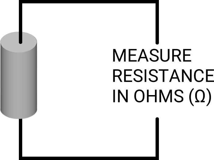
The electrical resistance (R) of an object is measured in Ohms and represented by the Greek letter Ω (omega). The resistance of a metal or a semiconductor can be measured using an ohmmeter (a common function on benchtop multimeters). The measurement of an object’s resistance can be taken with such a meter independent of the dimensions of the object or the object’s internal composition.
Figure 1: Resistance of an object
Three factors contribute to an object’s overall resistance. It is intuitive that a longer object is more resistive to electrical flow, as the electrons have farther to travel. Similarly, a narrower object is more resistive to flow, as there are fewer parallel pathways for the electrons to travel down. Finally, an object that has a material more intrinsically resistant to the flow of electrons will be more resistive. This intrinsic characteristic of a material that makes it conductive to the flow of electrons is called resistivity.
Therefore, we can say that electrical resistance (R) of an object is a result of three factors:
- Cross-sectional area of an object (A)
- Length of the object (L)
- Intrinsic properties of the material the object is composed of—resistivity (ρ)
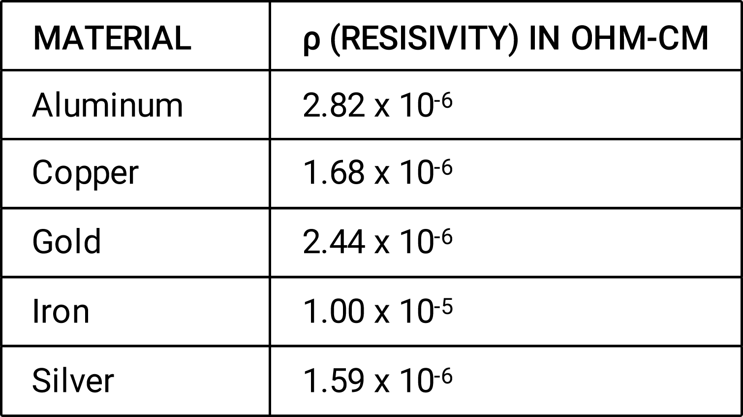
To determine the resistivity of various materials, objects composed of different materials but with the same dimensions were tested for their resistance. Table 1 shows the resistivities of some common materials.
Table 1: Resistivities of various materials
From these observations about the three factors of resistance, we conclude that resistance equals resistivity (ρ) times length (L), divided by area (A), as demonstrated by Figure 2 and Equation 1.
Figure 2: Resistance is a function of resistivity (ρ), length (L), and area (A)
Equation 1: Formula for resistance
R = ρxLA
In order to find the sheet resistance of an object, think of a square shape cut out of a doped silicon wafer, conductive film sheet, or a coated glass panel. We don’t want to have to worry about length and width along the entire plane of the material. This can be avoided by assuming a square shape. Now let’s describe the square as having a length (L), width (W), and thickness (T), as shown in Figure 3 below.
Figure 3: Sheet of resistive material
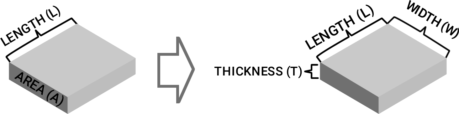
Next, let’s take our formula that relates length, area, and resistivity to resistance and transform it. This is done by substituting area (A) with width (W) times thickness (T).
Equation 2: Transforming resistance equation
R = ρxL A ⇒ R = ρxL LxW
Finally, since the material in this example is a perfect square, we can substitute length (L) for width (W). This results in the equation: Sheet resistance (Rs) equals resistivity (ρ) divided by thickness (T).
Equation 3: Formula for sheet resistance
Let L =W and consider Rs
Rs = ρxL TxL ⇒ Rs = ρ T
Why measure emissivity
The goal of Low E glass manufacturers is to achieve the highest possible reflectance of infrared radiation. This can be alternatively stated as the goal of achieving the lowest possible emissivity of thermal radiation through the glass.
Radiation from the sun includes electromagnetic waves at various frequencies. When this wave hits uncoated glass, most of its energy is preserved and is transmitted through the glass. However, when certain frequencies of this wave hit the semiconductive or metallic layer of Low E glass such as ITO, FTO, Ag, or Au, certain wavelengths pass through the glass while others are blocked or dissipated. This occurs because Low E glass exploits the ability of these materials to transport electrons along their surface where the energy is converted into heat and dissipated outward. For this reason, a material’s ability to transport electrons (i.e. to conduct current) is positively related to a lower emissivity.
Emissivity as a function of sheet resistance
In order to find the specific relationship between sheet resistance and sheet conductance, we must refer to the theory of the propagation of electromagnetic waves in thin conductive coatings. Assuming wavelengths less than 3 micrometers (i.e λ > 3 µm) and a sufficiently low sheet resistance, we can say that normal emissivity is equal to four times sheet resistance divided by the impedance of vacuum as depicted in equation 4 below.
Equation 4: Equation for emissivity
εn = α n,IR = 1 -ρ n,IR = 4* R □ /Z 0
Knowing that the impedance of vacuum is 377 Ohms, the formula can be further simplified resulting in the statement that emissivity equals 0.0106 times sheet resistance.
Equation 5: Equation for emissivity as a function of sheet resistance
εn = 0.0106 *R □
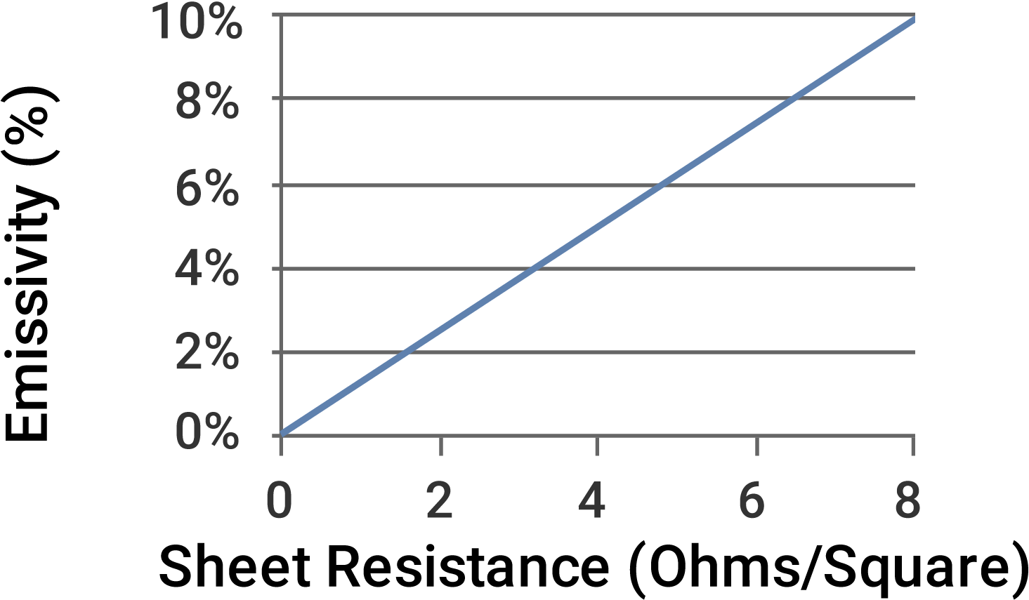
We can graph out this linear relationship and see an almost one-to-one correlation between sheet resistance (measured in Ohms/Square) and emissivity (%).
Figure 4: Emissivity vs Sheet Resistance
Manufacturers of Low E glass monitor and measure sheet resistance from research, through pilot production, through full production as the measurable proxy for emissivity. The target sheet resistance for various coatings is listed in table 2 below.
Table 2: Comparison of typical low E materials
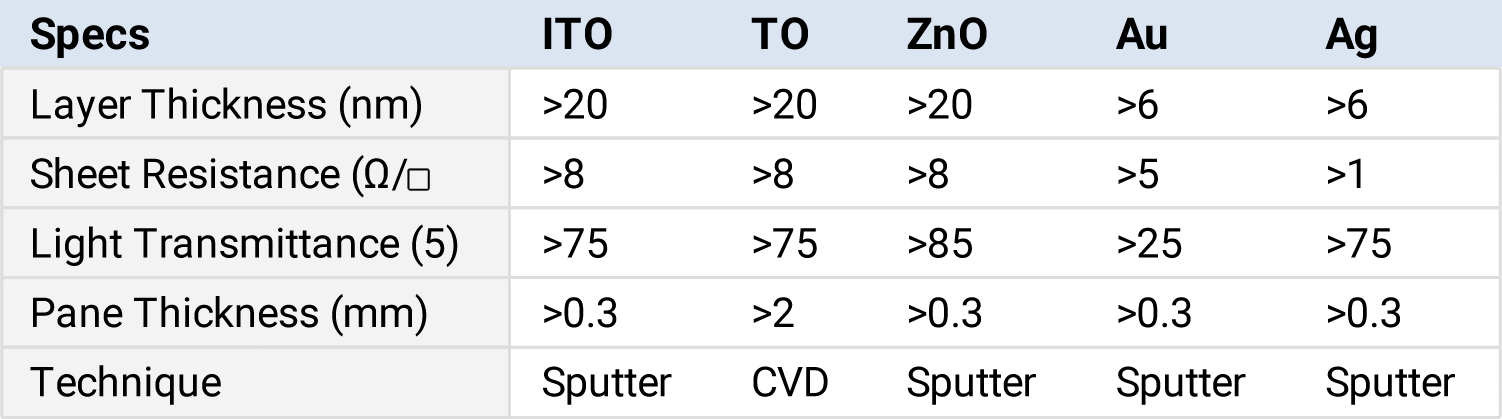
Chart curtesy of “Large Area Glass Coating” by Joachim Glasser, Von Ardenne Technik, 2000
Units of measurement
The unit of measurement for emissivity is dimensionless. Emissivity is a measure of the ratio of energy emitted by a surface to the energy that would be emitted by a blackbody at the same temperature and under the same conditions. Since it is a ratio, it does not have units of measure like meters, seconds, or joules. Instead, it is usually expressed as a number between 0 and 1, with 1 representing a blackbody, which is the most efficient emitter of thermal radiation, and 0 representing a perfect reflector, which does not emit any radiation.
Applications that measure/monitor sheet resistance
- Low E Glass
- Smart Glass
- Auto Mirrors
How eddy current instruments measure emissivity
Eddy current meters work by introducing a current into the sensor’s inductor coil(s). This generates an oscillating magnetic field. When a conductive material is introduced into the magnetic field, a circular flow of electrons begins to move in the conductive layer due to magnetic induction. Eddy current technology earned its name because this flow of electrons is reminiscent of eddy current swirls in a body of water.
An eddy current instrument works by coupling the material to be tested to an amplitude stabilized oscillator. The power absorbed by the material in the oscillating magnetic field is proportional to the conductivity of the material. This power level is delivered as voltage to an analog-to-digital converter (ADC). This voltage is scaled from 0.0001 to 2.0000 voltage direct current (VDC). For a standard range meter, .0001 VDC is equal to .0001 Siemens/square.
The eddy current meter then digitally reciprocates sheet conductance (measured in Siemens/square) to display values as sheet resistance (measured in ohms/square). The sheet resistance value is then multiplied by 0.0106 resulting in an emissivity value.
Configuring your instrument to display emissivity
Eddy current meters work by introducing a current into the sensor’s inductor coil(s). This generates an oscillating magnetic field. When a conductive material is introduced into the magnetic field, a circular flow of electrons begins to move in the conductive layer due to magnetic induction. Eddy current technology earned its name because this flow of electrons is reminiscent of eddy current swirls in a body of water.
An eddy current instrument works by coupling the material to be tested to an amplitude stabilized oscillator. The power absorbed by the material in the oscillating magnetic field is proportional to the conductivity of the material. This power level is delivered as voltage to an analog-to-digital converter (ADC). This voltage is scaled from 0.0001 to 2.0000 voltage direct current (VDC). For a standard range meter, .0001 VDC is equal to .0001 Siemens/square.
The eddy current meter then digitally reciprocates sheet conductance (measured in Siemens/square) to display values as sheet resistance (measured in ohms/square). The sheet resistance value is then multiplied by 0.0106 resulting in an emissivity value.