 Veteran Owned
 Veteran Owned
Low E Glass
What is Measured
Delcom sheet resistance meters are most often used to measure the active layer of Low-E glass. This includes both metal coatings such as Silver (Au) and Gold (Ag) and semiconductive coatings such as Indium Tin Oxide (ITO) and Fluorine-doped tin oxide (FTO).
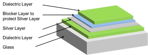
Figure 1: Possible Low E Glass cross-section
Delcom sensors are used extensively in the Low-E industry because sheet resistance approximates emissivity.
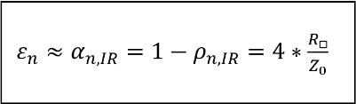
Assuming wavelengths more than 3 micrometers (i.e λ > 3 µm) and a sufficiently low sheet resistance, we can say that normal emissivity approximates four times sheet resistance divided by the impedance of vacuum.
Figure 2: Equation for emissivity
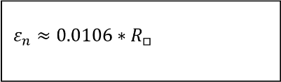
Knowing that the impedance of vacuum is 377 Ohms, the formula can be further simplified resulting in the statement that emissivity approximates 0.0106 times sheet resistance.
Figure 3: Equation for emissivity as a function of sheet resistance
Of course, each researcher/production manager has their own constant that they are comfortable with. Delcom software allows for users to designate their own constant and observe readings on the Delcom meter in units of emissivity.
Why Measure with Delcom
It is important to note that because eddy current meters rely on a magnetic field to achieve their reading, they have a number of advantages over four-point probes to include:
- Reliably approximates emissivity
- Is non-destructive
- Reads through insulating layers
- Measures moving material
- Provides nearly instantaneous readings
- Provides real-time process inspection
Employment Strategies
Low-E glass manufacturing faces a number of challenges to include:
- Problems caused by curing, annealing, temperature change, and other processes changing the sheet resistance over the course of production that needs to be carefully monitored
- Cross-web consistency born of using multiple targets or other segmented deposition techniques
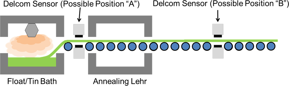
For those customers manufacturing Passive Low-E glass, a hard coat pyrolytic process of applying a tin oxide or silver layer (Chemical Vapor Deposition when performed in vacuum) is employed. In such a process, a Delcom sensor can be deployed before or after annealing. Regardless of placement, efforts must be made to shield the sensor from the high radiant heat of the glass and equipment. In addition to shielding, the cooling line option might be needed to ensure the Delcom sensor does not overheat.
Figure 4: Possible sensor locations for hard coating process
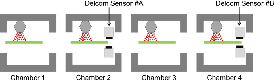
For those producing solar control Low-e and passive Low-E glass, an off-line soft coating process is often used. This process occurs after the glass ribbon has been cut into stock sheets, occurs at room temperature under vacuum, and employes Magnetron Sputter Vacuum Deposition (MSVD) to apply a thin transparent coating of tin oxide or silver. If a Soft Coat manufacturing process is being employed, any Delcom vacuum-ready sensor can be employed in nearly any location.
Figure 5: In-situ monitoring for a soft coating process (including possible positions for Delcom Sensors):
Cross-Web & Downstream Monitoring
In general, Delcom sensor deployment strategies can include one or more of the following deployment tactics.
|
Deployment Strategy |
Image | Advantages |
|---|---|---|
| Single sensor single spot |  |
|
| Two sensors monitoring cross-web | 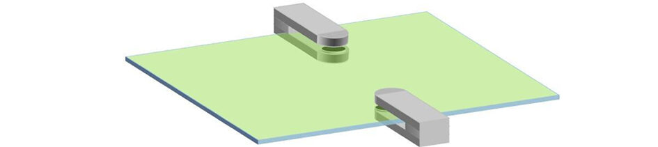 |
|
| Two sensors monitoring downstream | 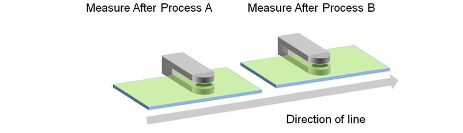 |
|
| Multi-channel monitoring cross-web | 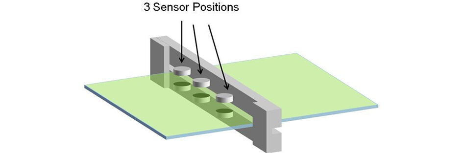 |
|
Recommended Sensors
Delcom recommends the following sensors based on the user’s material, stage of development, and application.
| Use case | Image | Recommended Sensor | Use case |
|---|---|---|---|
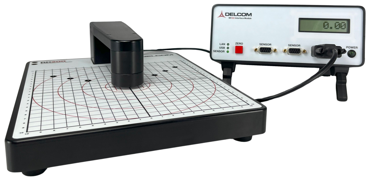
| Benchtop |  |
RD200 |
|
| Benchtop | 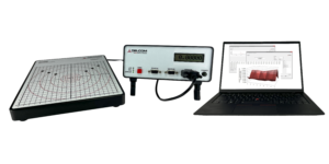 |
RS200 |
|
| Benchtop |  |
RD300 |
|
| Benchtop | 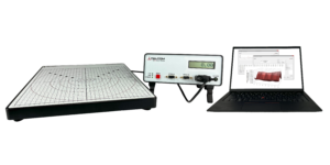 |
RS300 |
|
| Benchtop | 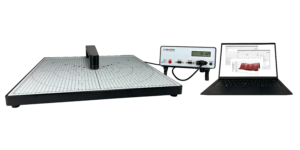 |
RD450 |
|
| Benchtop | 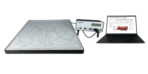 |
RS450 |
|
| Inline | 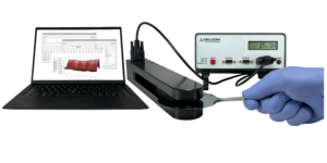 |
20J3 Hybrid |
|
| Inline | 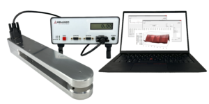 |
20J3 Inline |
|
| Inline | 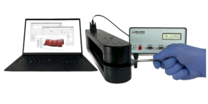 |
30C9 Hybrid |
|
| Inline | 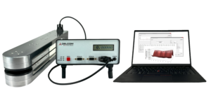 |
30C9 Inline |
|
| Inline | 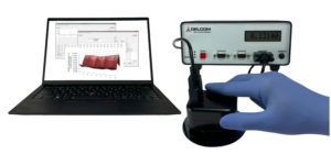 |
S3 Hybrid |
|
| Inline |  |
S3 Inline |
|
| Inline | 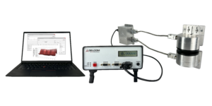 |
OEM |
|
| Inline | 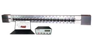 |
Multisensor |
|
Recommended Sensor Range
Delcom sensors measure sheet resistance in Ohms/square, therefore ranges of our instruments stated in terms of emissivity require multiplication by the user’s preferred constant. Below are Delcom sensor ranges restated in units of emissivity assuming a constant of 0.0106.
Figure 6: Delcom sensors are available in the following ranges
| Range Name | Min Sheet Resistance in ohms/square |
Max Sheet Resistance in ohms/square |
Min Emissivity | Max Emissivity |
|---|---|---|---|---|
| x10 | 5 | 100000 | 0.053 | 1060 |
| x1 | 0.5 | 10000 | 0.0053 | 106 |
| ÷10 | 0.05 | 1000 | 0.00053 | 10.6 |
| ÷100 | 0.005 | 100 | 0.000053 | 1.06 |
Low E Glass products typically have a target sheet resistance of between 1 and 8 ohms/square. Therefore, the recommended instrument range for this application is “x1”.